Meet this line on a drawing:
Looks like alphabet soup? Not for long. Let’s read it one piece at a time:
4X
Four identical features. In this example, four holes.
Ø.50
The Ø means diameter—how wide the hole is across its center. If the print uses inches, .50 means half an inch.
THRU
The hole goes all the way through the material.
Put it together
Four half-inch-wide holes, all the way through the part (if the drawing uses inches).
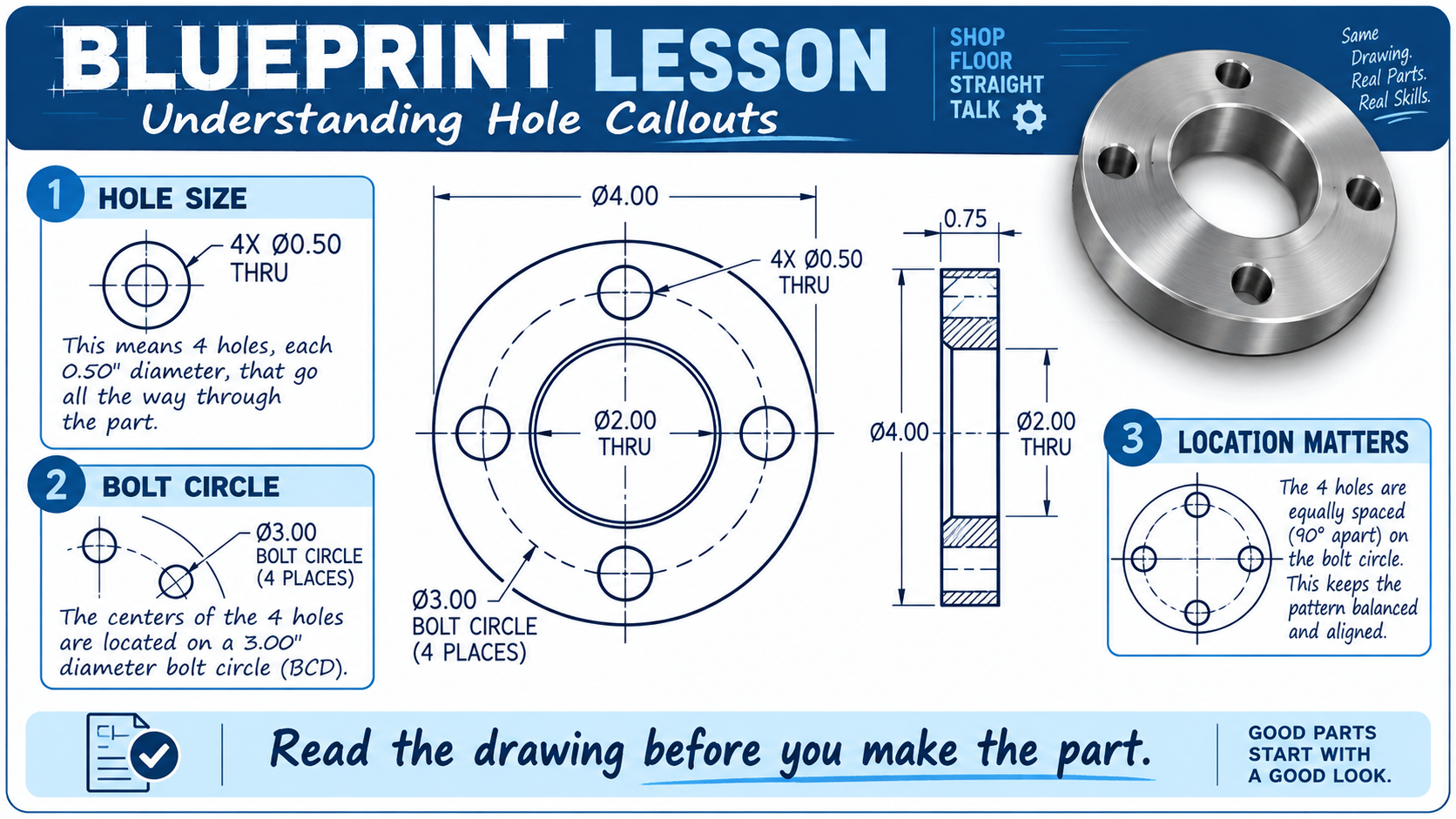
Okay, so where do the holes go?
That's a different question. The hole callout tells you their size and depth; it doesn't fully define their locations by itself.
Our example has a Ø3.00 bolt circle: each hole center sits on an imaginary circle that's 3 inches in diameter. If the drawing also specifies four holes equally spaced around the circle, their nominal angular spacing is 90°.
Don't confuse nominal size with tolerance
The callout shows a nominal diameter. The allowed variation in hole diameter comes from the drawing's applicable size tolerance, which may be specified next to the dimension or in general notes/title-block tolerances.
But the hole can be the perfect size and still be in the wrong spot. The drawing must also tell you where the holes belong and how much their locations are allowed to vary. A bolt-circle dimension alone does not tell you every acceptable location limit.
Quick check: did it stick?
Keep the new guy off the scrap pile.
Next lesson: what to look at before you ever start making parts.
NEXT: CHECK THE PRINT →Note: This lesson uses a simplified example. Interpret customer drawings using their designated drawing standard, datum scheme, feature controls and applicable specifications.